
Product specification
Air-cooled energy storage system -300KW-723KWh
![]()
HV-CBT300-723-Ver1.0
Due to product version upgrades, iterations, or other reasons, the content of this manual may be updated and revised periodically, but there may be slight discrepancies or errors with the actual product. This document serves only as a guide for use, and the statements, information, and recommendations contained herein do not constitute any express or implied warranties.
The images described in this manual are for reference only, and the actual product shall prevail.
1 Product Introduction
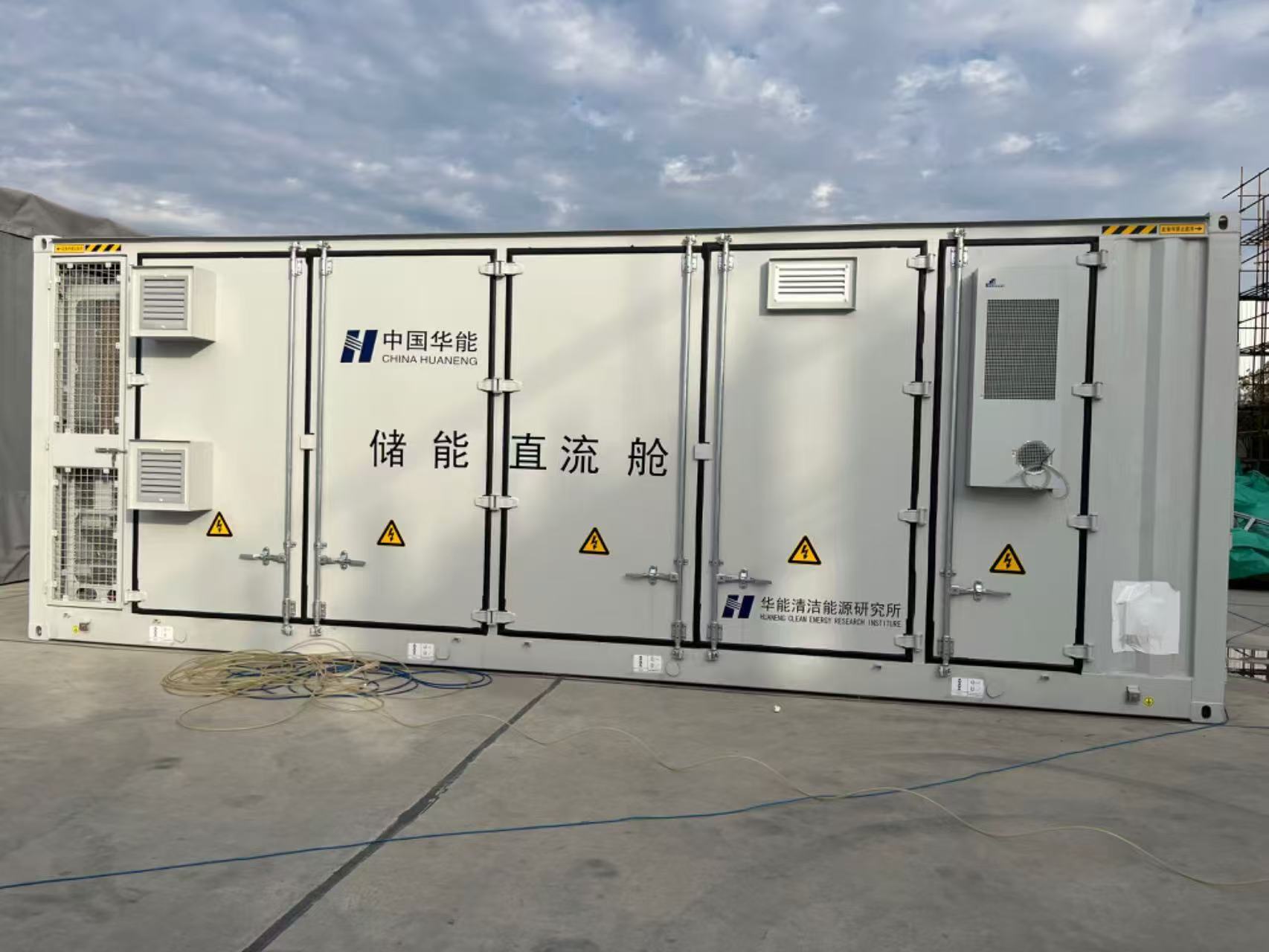
This product specification sheet is only applicable to this type of energy storage product. Product model: HV-CBT300-723
This product is a commercial and industrial energy storage system, equipped with a 300KW/723KWH energy storage system, supporting up to 360KW photovoltaic access, with and off grid switching, suitable for unstable areas of the power grid, with complete fire/safety protection mechanisms, supporting remote monitoring and control, and energy statistics function
2 Product functional parameters
2.1 Product Composition
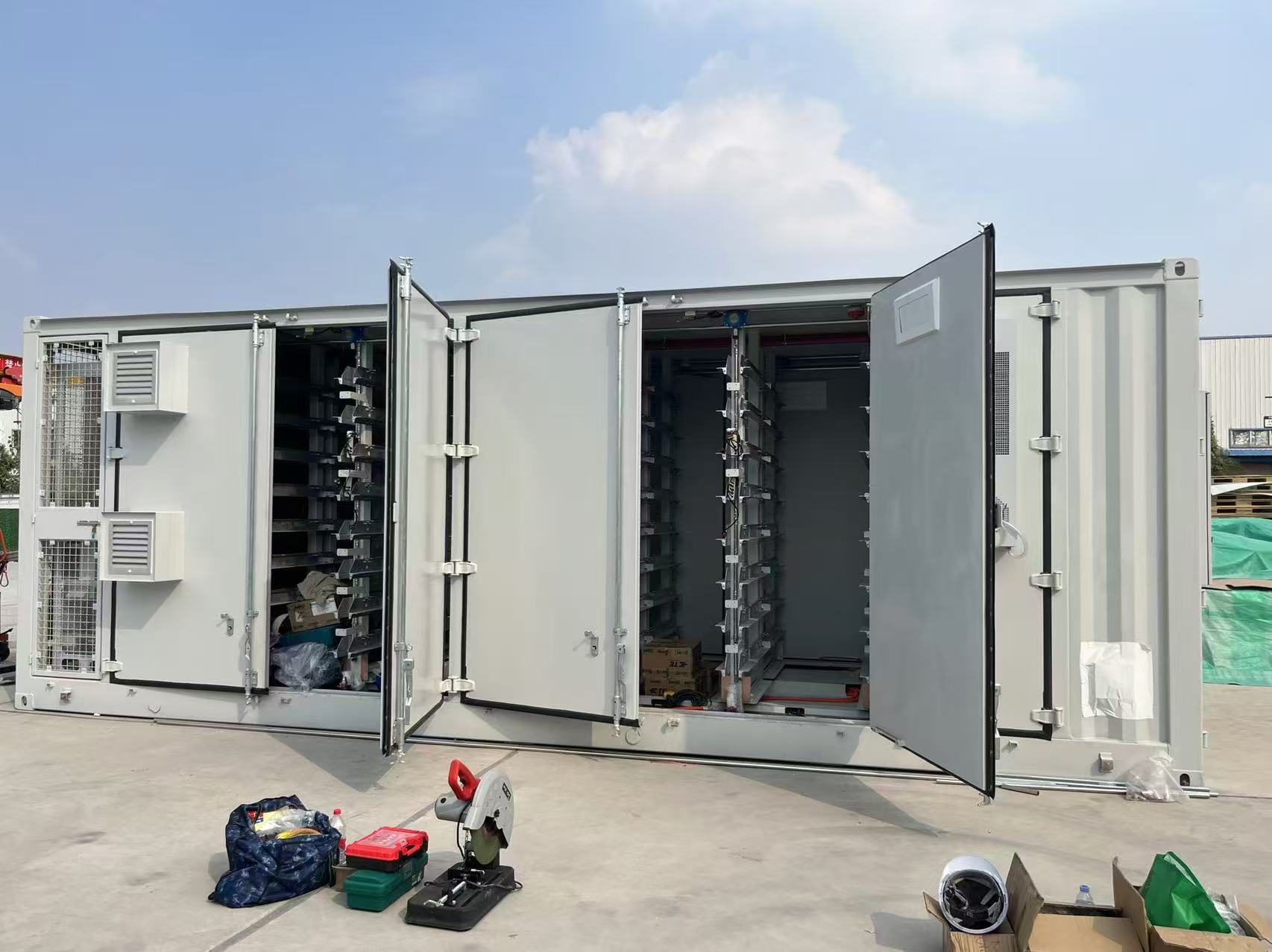
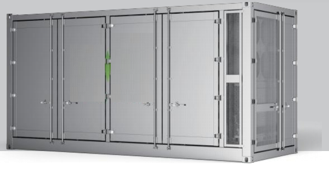
The energy storage system of -300KW/723KWH mainly consists of 3 air-cooled 241KWh high-voltage batteries, 3 sets of 100KW PCS, 1 air-cooled host, distribution and cabinet structure electrical auxiliary equipment, etc. It supports 0.5C charging and discharging.
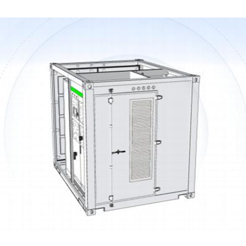
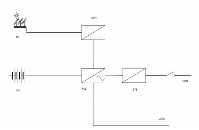
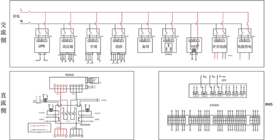
The system diagram is shown in the following figure:
Figure 1 System schematic diagram
2.2 Core components of the product
2.2.1 Product Battery Cells
The product adopts square shell LFP battery cells and 1P24S grouping method, with 10 modules forming a 10 * 1P24S module pack as the core energy storage product of the product.
Through safety tests such as overcharge, overdischarge, compression, drop, and short circuit.
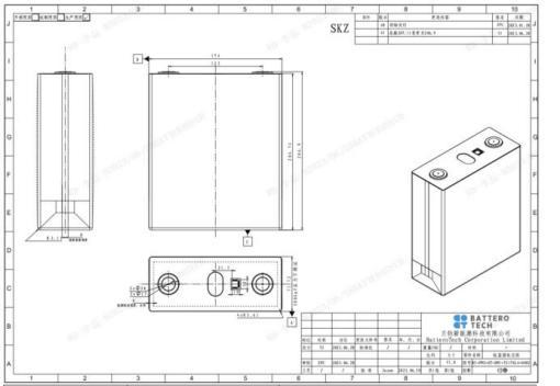
Figure 4.3 Cell size diagram
Table 4.2 Cell Size Parameters Table
|
project |
describe |
Size (mm) |
|
W |
width |
174±0.5 |
|
T |
thickness |
71.72±0.5 |
|
H |
height |
204.7 ± 0.8 (shoulder height) 206.9 ± 0.5 (total height) |
|
Weldable area |
Pole diameter |
φ17±0.5 |
|
Welding penetration depth |
depth |
≤2.0 |
|
Pole center distance |
distance |
123±0.3 |
Key parameters of battery cells
The key parameters of the battery cell are as follows.
Table 4.3 Specification Parameters of Battery Cells
|
Serial number |
Sub item |
index |
remarks |
|
1 |
Product specifications |
LPF-280Ah |
|
|
2 |
Nominal capacity |
280Ah |
Standard charging and discharging mode |
|
3 |
Nominal energy |
896Wh |
Standard charging and discharging mode |
|
4 |
Working voltage range |
2.5~3.65V 2.0~3.65V |
Cell temperature T>0 ° C Cell temperature T ≤ 0 ° C |
|
5 |
Self discharge |
≤ 3%/month |
30% SOC, stored at 25 ± 2 ℃ |
|
6 |
Working environment temperature range |
Charging: 0~60 ℃ Discharge: -30~60 ℃ |
|
|
7 |
Battery size |
72*174*208mm |
|
|
8 |
Cell weight |
5.4±0.15kg |
|
|
9 |
energy density |
170Wh/kg |
|
|
10 |
internal impedance |
≤0.25mΩ |
Fresh battery cells (20~40% SOC) tested at 1kHz AC |
|
11 |
High temperature discharge capacity |
≥280Ah |
25±2°C , Charge 1P constant current to 3.65V and let it stand for 1 minute, charge 0.1P constant current to 3.65V; Let it stand at 55 ± 2 ° C for 120 minutes, Discharge 1P to 2.5V |
|
12 |
Low temperature discharge capacity |
≥224Ah |
25±2°C , Charge 1P constant current to 3.65V and let it stand for 1 minute, charge 0.1P constant current to 3.65V- Let it stand at 20 ± 2 ° C for 120 minutes, Discharge 1P to 2.0V |
|
13 |
Lifetime demand |
≥8000 Cycle |
Initial clamping force of 300 ± 20Kgf at 25 ± 2 ° C, Gap0.5~1.0mm , Standard charge and discharge test 25 ± 2 ° C @ 70% EOL |
2.2.2 BMS
As the core component of energy storage systems for collection, control, and protection, BMS is divided into a three-level architecture, including
BAU , B C U , B M U
BAU conducts comprehensive management and coordination of multi cluster battery systems. It integrates the functions of BMU and BCU, and has more advanced features such as fault diagnosis and warning, system status assessment, etc. BAU can also communicate with external systems to achieve remote monitoring and management
BCU is generally placed in the high-voltage box of the battery cluster to achieve real-time monitoring of the total voltage, total current, insulation resistance, and internal temperature of the high-voltage box of the battery cluster. At the same time, it summarizes the voltage, temperature, and other information of individual cells in the cluster to estimate the SOC/SOH of the battery cluster, perform balancing strategy judgment, battery fault diagnosis and alarm, and realize on-site protection and relay control of the battery cluster based on the battery fault information. Finally, it exchanges information with EMS, PCS and other equipment through CAN/RS485 communication interface. When the battery cluster experiences serious overvoltage, undervoltage, overcurrent (short circuit), overheating, leakage (insulation) and other abnormal faults, the BCU can effectively control the disconnection of the battery cluster, avoiding overcharging, overdischarging, overheating, overcurrent, and ensuring the efficient, reliable, and safe operation of the energy storage system.
BMU provides real-time monitoring of single cell battery voltage and temperature, as well as balancing capability. It forms a highly flexible battery management system (BMS) through daisy chain communication and battery cluster management unit (BCU).
2.2.2.1 Main functions of BCU
The main control unit is mainly composed of the following parts: auxiliary power conversion, MCU and peripheral circuits, real-time clock, total voltage and insulation monitoring, charge and discharge current detection, external relay (contactor) drive and detection, communication interface, etc. The main functions include: detection of total voltage of the battery pack, detection of charging and discharging current of the battery pack, detection of insulation resistance of the battery pack to ground, management of battery pack charging and discharging, thermal management of the battery pack, real-time dynamic estimation of SOC and SOH, system self check and fault diagnosis alarm, safety protection for various abnormal and fault situations, communication with other devices such as PCS and EMS, data storage, transmission and processing, storage of recent alarm information, reset information, and sampling abnormal information of the system. The stored information can be exported as needed. During the charging and discharging process of the system, the temperature of individual cells is monitored, and there are alarms for high or low cell temperature, or large temperature difference between cells. When a second level alarm occurs, the alarm information is actively reported. When a third level alarm occurs, the system automatically cuts off the contactor.
Table 4.4 Main functional parameters of BCU
|
Serial number |
project |
parameter |
remarks |
|
1 |
Working voltage range |
9-32V |
|
|
2 |
Working current |
80mA |
24V power supply, no external load |
|
3 |
CAN communication interface |
2 routes |
quarantine |
|
4 |
RS485 communication interface |
3 routes |
quarantine |
|
5 |
Total pressure collection channels |
1 Road |
|
|
6 |
Total pressure collection range |
50-1500V |
|
|
7 |
Total pressure collection error |
±0.5% |
|
|
8 |
Diverter collection range |
-500~500A |
Depending on the range of the splitter |
|
9 |
Diverter acquisition error |
±0.5% |
Excluding the error of the splitter itself |
|
10 |
Number of Hall current acquisition channels |
3 routes |
Supports voltage type Hall, CAN Hall, current type Hall, and three types of Hall respectively |
|
11 |
Number of temperature collection channels |
Route 6 |
|
|
12 |
Temperature collection range |
-40~125℃ |
|
|
13 |
Temperature acquisition error |
±1℃ |
|
|
14 |
High side switch output |
Route 8 |
|
|
15 |
High voltage relay status check |
2 routes |
|
|
16 |
Digital input/output |
Route 7 |
7-way IO input/output status can be flexibly configured |
|
17 |
SOX estimation |
±5% |
|
|
18 |
Working temperature range |
-25~65℃ |
|
|
19 |
Working humidity |
5%~95% |
|
|
20 |
Working altitude |
≤4000m |
|
2.2.2.2 Main functions of BMU
The main functions of BMU include: battery cell voltage function, temperature sampling function, passive balancing function, isoSPI communication, 485 communication function, rich self diagnostic function, and support for functional safety certification requirements.
Table 4.5 Main functional parameters of BMU
|
Serial number |
project |
parameter |
remarks |
|
1 |
Working voltage range |
9-32V |
|
|
2 |
Working current |
10mA |
24V power supply, no external load |
|
3 |
Number of individual voltage acquisition strings |
64 strings |
|
|
4 |
Single cell voltage acquisition range |
0-5V |
|
|
5 |
Individual voltage acquisition accuracy |
±3mV |
Range of 2.5V to 4.5V, -30-85 ℃ |
|
6 |
Balanced current |
100mA |
Passive equilibrium |
|
7 |
Number of battery temperature collection channels |
Route 52 |
Excluding the error of the splitter itself |
|
8 |
Battery temperature collection range |
-40~125℃ |
|
|
9 |
Accuracy of battery temperature acquisition |
±2℃ |
|
|
10 |
Working power consumption |
3.4mA |
|
|
11 |
Sleep power consumption |
5uA |
|
|
12 |
insulation resistance |
100MΩ |
|
|
13 |
Voltage resistance |
3000Vac |
|
2.2.2.3 Main functions of combiner cabinet/BAU
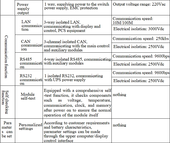
A combiner cabinet is a control cabinet that connects battery clusters with PCS energy storage inverters, EMS systems, and dynamic environmental monitoring equipment (fire/air conditioning/access control). It is equipped with a large storage system battery stack circuit breaker (live operation), UPS power supply, large storage main control module, large storage display and control module, emergency stop switch, etc., to achieve charging and discharging control, protection, and data communication functions for lithium energy storage battery stacks.
Product Features
1. Support 220Vac power input to supply power to the UPS inside the combiner cabinet;
2. UPS supplies power to the switch power supply (220Vac), which is converted by the switch power supply to supply power to the main control module and display control module (recommended 24Vdc);
3. Support power supply to the high-voltage box, with a supply voltage of 220Vac, indirectly supplying power to the main control module (recommended 24Vdc);
4. Support communication with PCS inverters, EMS systems, dynamic environmental monitoring equipment, etc;
5. Support the opening and closing control and status monitoring of circuit breakers, and display the status through indicator lights;
6. Summarize real-time data information of the entire system, support battery stack status data processing, and achieve management and control of battery charging and discharging after processing;
7. Support emergency stop control function. In case of emergency, press the emergency stop switch button on the outside of the cabinet to stop the operation of the entire energy storage system;
8. Support LED status indication for combiner cabinets, including four status indicator lights for operation, fault, communication, and insulation;
The BAU main control module installed in the combiner cabinet has isolated LAN, CAN, RS485, RS232, TF card, and USB interfaces, enabling communication, data storage, and protection with the BCU main control module, MM10 display and control module, PCS inverter, EMS system, and dynamic environmental monitoring equipment. It can also store internal data, operational data, and power failure data, and support program upgrades and data exports;
10. The MM10 display and control module installed in the combiner cabinet has isolated LAN, micro USB, USB, TF card interfaces, and 10 A 1-inch display screen that enables communication with the SCU control module and displays data for the entire battery system;
11. Equipped with overvoltage, undervoltage, pressure difference, overcurrent, undercurrent, overtemperature, undertemperature, temperature difference of batteries (single cells, modules, clusters, stacks)
Alarm and protection for short circuit, insulation, relay diagnosis, etc;
12. The product complies with the EU RoHS directive, IEC/EN/UL 62368, and IEC/EN/UL 60730 requirements.
Standard Electrical Schematic Diagram
Technical specifications of combiner cabinet
2.2.3 PCS module
The outdoor cabinet type energy storage system adopts a modular solution, and users can configure different numbers of power modules according to project requirements. The parameters of the communication module are as follows:
|
S/N |
project |
parameter |
remarks |
|
1 |
model |
Monet -125AC |
|
|
2 |
Rated power |
125kW |
|
|
3 |
maximum power |
137kW |
|
|
4 |
DC working voltage range |
580V~1000V (three-phase three wire) |
|
|
5 |
DC side full load voltage range |
625V~1000V (three-phase three wire) |
|
|
6 |
Maximum direct current current |
680V~1000V (three-phase four wire) |
|
|
7 |
Rated AC voltage |
400Vac ,3W+N+PE/3W+PE |
|
|
8 |
Rated frequency |
50/60Hz, ( ±5Hz) |
|
|
9 |
Rated AC current |
180A |
|
|
10 |
Overload capacity |
110%, operating normally; 120%, 1 minute; |
|
|
11 |
Current distortion degree |
<3% (rated power) |
|
|
12 |
Power factor adjustment range |
-1 leading++1 lagging |
|
|
13 |
Working mode |
Constant current, constant power, MPPT, AC voltage source |
|
|
14 |
Maximum efficiency |
99% |
|
|
15 |
Dimensions (W * D * H) |
566 (excluding installation ears 520) * 680 * 245mm |
|
|
16 |
Weight (approximately) |
68kg |
|
|
17 |
Isolation method |
Non isolated |
|
|
18 |
Anti corrosion grade |
C3 |
|
|
19 |
Protection level |
IP20 |
|
|
20 |
working temperature |
-30 ° C~+60 ° C (>45 ° C derating) |
|
|
21 |
relative humidity |
0~100% (non condensing) |
|
|
22 |
Cooling method |
Intelligent air cooling |
|
|
23 |
noise |
<75dB |
|
|
24 |
Altitude |
3000m (>3000m derating) |
|
|
25 |
communication interface |
RS485/CAN2.0/dry contact |
|
2.2.4 MPPT module
|
model |
Monet-60DC |
|
Rated power |
60kW |
|
maximum power |
66kW |
|
DC voltage operating range |
200~1000V |
|
High voltage side full load voltage range |
545~950V |
|
Maximum current on the high voltage side |
110A |
|
Low voltage side full load voltage range |
375~900V |
|
Maximum current on the low voltage side |
80A*2 |
|
Number of input channels on the low voltage side |
2 |
|
Compatible with batteries |
Photovoltaic/lithium battery/lead-acid/flow battery/DC bus/DC load, etc |
|
Working mode |
MPPT/constant power/constant voltage/constant current |
|
working temperature |
-25~60 ℃ (derating above 45 ℃) |
|
Maximum conversion efficiency |
98.8% |
|
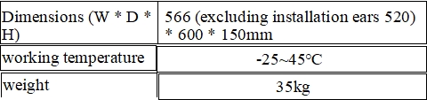
Dimensions (W * D * H) |
566 (excluding installation ears 520) * 600 * 150mm |
|
weight |
35kg |
2.2.5 STS module
|
model |
Monet-600STS |
|
Rated power |
600kW |
|
maximum power |
660kVA |
|
Rated AC voltage |
400Vac,3W+PE |
|
Rated frequency |
50/60Hz |
|
Rated AC current |
866A |
|
Switching time |
<10ms |
|
Synchronous control and protection interface |
CAN/I/O interface/CT input |
2.2.6 Air cooled unit
Working principle of air-cooled unit: When the temperature inside the cabin is higher than the cooling set point and meets the cooling start conditions When the unit starts cooling and selects different cooling capacities based on the actual temperature; When the temperature inside the cabin is lower than the cooling set point, the unit saves energy by turning off the compressor and other methods. When the temperature inside the cabin is lower than the heating set point and meets the heating activation conditions, the unit starts the electric heater. The functional parameters of the air-cooled unit are as follows:
|
S/N |
project |
parameter |
remarks |
|
1 |
model |
EC01031AT |
|
|
2 |
Rated working voltage |
380Vac |
|
|
3 |
Rated power |
12.5kW (cooling power: 12.5kW; heating power: 6kW) |
|
|
4 |
Rated operating frequency |
50/60Hz |
|
|
5 |
Size (H * W * D) |
700 ×1300 ×300 mm |
|
|
4 |
weight |
50kg |
|
|
5 |
Communication method |
RS485 |
|
|
6 |
Protection level |
IP55 |
|
|
7 |
Working mode |
Automatic control mode, cooling mode, heating mode |
|
|
8 |
Noise |
≤72dB |
|
|
9 |
Cooling start point |
0~99 ℃ (adjustable) |
|
|
10 |
Refrigeration hysteresis |
0~9 ℃ (default 3) |
|
|
11 |
Heating activation point |
0~99 ℃ (adjustable) |
|
|
12 |
Heating sensitivity |
0~9 ℃ (default 3) |
|
2.2.7 Fire Protection System
The use of aerosol fire extinguishing devices in the fire protection system is a new environmentally friendly fire protection product with world advanced level. Working principle: When the ambient temperature reaches the starting temperature of the thermal wire or comes into contact with an open flame, the thermal wire self ignites and is transmitted to the aerosol series fire extinguishing device. After receiving the start signal, the aerosol fire extinguishing device activates the internal fire extinguishing agent, rapidly producing nano aerosol fire extinguishing agent and spraying it out, achieving rapid fire extinguishing. The parameters of the fire protection system are as follows:
Table 4.8 Main Functional Parameters of Fire Protection System
|
|
Serial number |
project |
parameter |
remarks |
|
|
1 |
model |
QRR0.3G/S-Q |
|
||
|
2 |
Drug weight |
300g |
|
||
|
3 |
Equipment weight |
860g±30g |
|
||
|
4 |
Spray time |
≤14s |
|
||
|
5 |
External dimensions |
46*68.5*255mm |
|
||
|
4 |
Hot distance between nozzles |
The thermal spacing at 400 ℃, 200 ℃, and 75 ℃ is 0.05m, 0.12m, and 0.3m, respectively |
|
||
|
5 |
Actual fire extinguishing efficiency |
100g/m³~ 130g/m³ |
|
||
|
6 |
Working environment temperature range |
-50℃~+90℃ |
|
||
|
7 |
relative humidity |
≤95% |
|
||
|
|
|
|
|
|
|
|
|
|
|
|
||
|
|
|||||
2.2.8 Access control switch
The door opening status of the access control switch detection equipment. The parameters of the access control switch are as follows: Table 4.10 Main functional parameters of the access control switch
|
Serial number |
project |
parameter |
remarks |
|
1 |
Rated voltage |
AC-15 :380V DC-13 :220V |
|
|
2 |
Rated current |
AC-15 :0.79A DC-13 :0. 14A |
|
|
3 |
Rated insulation voltage |
415V |
|
|
4 |
Rated impulse withstand voltage |
2.5kV |
|
|
5 |
Operating frequency |
Mechanical/Electrical: 20 times/minute |
|
|
6 |
Usage environment |
Temperature: -5 ℃~+40 ℃ Relative humidity < 90% RH (No condensation) |
|
2.2.9 Smoke detector
Smoke detectors are used to detect the smoke concentration in the current environment. The parameters of the smoke detector are as follows: Table 4.11 Smoke
Main functional parameters of the detector
|
Serial number |
project |
parameter |
remarks |
|
1 |
working voltage |
DC12/24V (allowable range 9V~30V) |
|
|
2 |
Working current |
Monitoring status:< 1mA@DC12V |
|
|
3 |
Relay output |
Normally open, contact capacity 1A 30VDC |
|
|
4 |
Work instructions |
The monitoring status red light flashes approximately once every 6 seconds The red light of the alarm status is always on The fault status red light flashes continuously twice every 6 seconds |
|
|
5 |
Usage environment |
Temperature: -10 ℃~+65 ℃ Relative humidity < 95% RH |
|
2.2. 10 Local Energy Management Systems
The Local Energy Management System (ESS) is an intelligent energy management system developed by our company for microgrid systems, mainly used in various capacity energy storage power stations and integrated photovoltaic storage and charging power stations. The product integrates human-machine configuration screen (HMI), port control and communication, system parameters and operation strategy setting functions to achieve monitoring and management of energy storage systems. The hardware resources and parameters of the product are as follows: monitoring host, including data acquisition, communication, local display, control equipment operation monitoring, coordination control, and energy management software.
Table 4 12 Main functional parameters of local controller
|
Serial number |
project |
parameter |
remarks |
|
1 |
model |
ESS |
|
|
2 |
Power input |
DC 12-24V |
|
|
3 |
Output control |
3-channel isolated output switch quantity |
|
|
4 |
Input control |
6-way isolated input switch quantity |
|
|
5 |
Serial communication |
2-channel isolated RS232, 4-channel isolated RS485 |
|
|
4 |
field bus |
2-channel CAN bus interface |
|
|
5 |
Ethernet port |
1-channel 10/100M Ethernet port (RJ45) |
|
|
6 |
Expand storage |
1 USB port, 1 SD card slot |
|
|
7 |
Audio alarm |
1 controllable buzzer |
|
|
8 |
Program characterization |
1 running indicator light, 1 status indicator light, 1 |
|
|
9 |
Abnormal characterization |
1 hardware watchdog timer |
|
|
10 |
Real time clock |
1 set of RTC real-time clock |
|
3 Product Features
This system has the following characteristics:
1. Safety
-Intelligent air-cooled temperature control system ensures consistent battery temperature control and is suitable for most regions;
-The system has been verified through multiple destructive tests such as short circuit, fire, and fire resistance, ensuring the safety and reliability of the product;
-Multi dimensional electrical fusion perception, multi-level fuse protection;
-Adopting the design concept of early thermal runaway risk warning, it integrates detection, fire extinguishing, combustible gas detection, smoke control, and explosion venting functions, and is linked with BMS and EMS for protection, ensuring the safe operation of energy storage;
-Adopting a full "mirror" surface design, with no protruding core components, providing safety protection and reducing the risk of hidden faults;
-High protection, system protection level IP55, suitable for various environments.
-Ultra stable design to cope with harsh outdoor working conditions
2. Minimalism
-The product adopts anti installation short circuit error and anti mistake design, which is convenient for safe maintenance;
-Aviation plug, plug and play, easy to expand hand in hand parallel;
-Overall delivery, factory prefabrication, and transportation of the entire machine for easy installation and maintenance, reducing transportation, installation, and commissioning costs by 15%.
3. Intelligence
-Cloud platform management system, supporting remote/local monitoring, intelligent cloud operation and maintenance without expert on-site maintenance;
-Intelligent balancing strategy, system AI warning, ensuring consistency throughout the battery life cycle;
-Support black start function, reliable power supply in off grid/microgrid mode;
4. Product specifications and parameters
The specifications and parameters of the battery compartment are shown in Table 1:
Table 1 Specification Parameters
|
Serial number |
category |
name |
parameter |
remarks |
|
1 |
Battery parameters |
Cell type |
LFP-3.2V-314Ah |
|
|
Rated capacity of battery [KWh] |
241 |
3 clusters totaling 723KWH |
||
|
Nominal voltage [Vdc] |
768 |
Voltage range 680-864 |
||
|
Charge discharge rate |
≤0.5CP |
|
||
|
Cooling method |
Intelligent air cooling |
|
||
|
2 |
Communication parameters (parallel/off grid) |
Rated power |
375KW |
|
|
Grid voltage |
380V/400V(-10%~10%) |
3W+PE/3W+N+PE |
||
|
Rated current |
540A |
|
||
|
Rated grid frequency |
50Hz/60Hz |
|
||
|
Grid frequency range |
50Hz/60Hz |
|
||
|
Total current waveform distortion rate |
<3% (rated power) |
|
||
|
power factor |
>0.99 (rated power) |
|
||
|
Adjustable range of power factor |
-1 (leading)~1 (lagging) |
|
||
|
3 |
Photovoltaic parameters |
Design capacity |
360KW |
|
|
Number of input channels |
6 |
|
||
|
Standard access parameters |
600V100A |
Maximum 160A |
||
|
Recommend single channel serial parallel connection |
8P12S*6 |
Single 55KW |
||
|
Working temperature range [℃] |
-15 ~ +45 |
|
||
|
4 |
system parameter |
Cooling method |
Air cooling |
|
|
Fire protection system |
Perfluorohexane |
|
||
|
Anti corrosion grade |
C3 |
|
||
|
Protection level |
IP55 |
|
||
|
Working temperature range [℃] |
-15 ~ +45 |
|
||
|
Storage temperature [℃] |
-20 ~ +45 |
SOC@30 %~50%,<6 months |
||
|
Working humidity range |
0~95%RH |
No condensation |
||
|
Installation method |
Outdoor installation |
|
||
|
working condition |
|
|
||
|
System communication interface |
Ethernet/RS485 |
|
||
|
External System Communication Protocol |
Modbus TCP /Modbus RTU |
|
||
|
Altitude [m] |
Within 2000m |
|
||
|
Size [mm] (W * D * H) |
2991*2438*2591 |
|
||
|
Weight [kg] |
8000KG |
|
||
|
authentication |
|
|
5. Configuration List
The battery cabinet configuration list is shown in Table 2:
Table 2 Battery Cabinet Configuration List
|
Serial number |
project |
quantity |
remarks |
|
1 |
High voltage battery |
3 |
Single unit 241KWH |
|
2 |
PCS |
3 |
Single unit 125KW |
|
3 |
MPPT |
6 |
Single unit 60KW |
|
4 |
STS |
1 |
600KW |
|
5 |
EMS |
1 |
|
|
6 |
Auxiliary power distribution |
1 |
|
|
7 |
Cables and others |
1 |
|
|
8 |
Air cooled air conditioner |
1 |
|
|
9 |
cabinet |
2 |
|
|
10 |
Surge protective device |
1 |
|
|
11 |
Three phase smart meter |
1 |
|
|
12 |
Perfluoroacetone fire extinguisher |
1 |
|
|
13 |
Switching Mode Power Supply |
1 |
|
|
14 |
Temperature sensor |
1 |
|
|
15 |
Access control sensor |
1 |
|
|
16 |
Water sensor |
1 |
|
|
17 |
Smoke sensor |
1 |
|
|
18 |
Cooling fan |
1 |
|
|
19 |
Circuit breaker |
N |
On demand configuration |
Previous :
Liquid cooled energy storage container-5MWHNext :
100kW / 215kWh All-in-One Air-cooled Energy Storage CabinetWe answer most inquiries in less than 3 hours during our normal business hours.
Categories

Ultra large capacity community energy storage and power supply system

For inquiries about our products or pricelist, please leave to us and we will be in touch within 24 hours.
 Room 1304 Building A Guanlan jieshun Technology Center GuanshengSechond Rd, Shenzhen, China