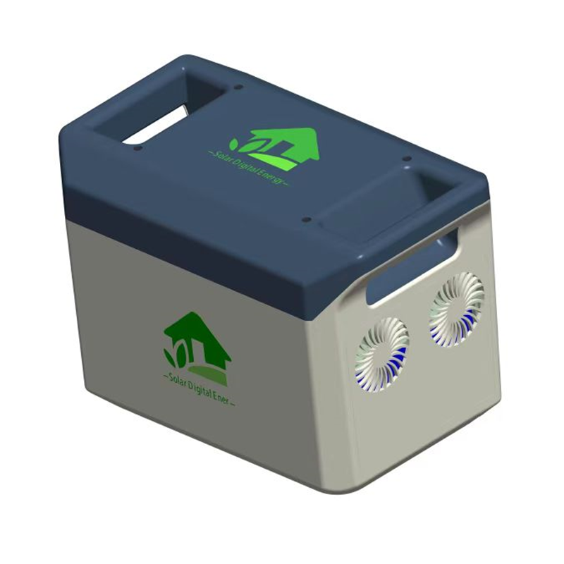

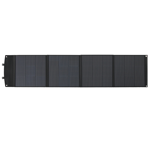
Portable home solar power system for home lighting and phone charging.
Easy installation, wide-ranging applications, preferential prices, and quality assurance.
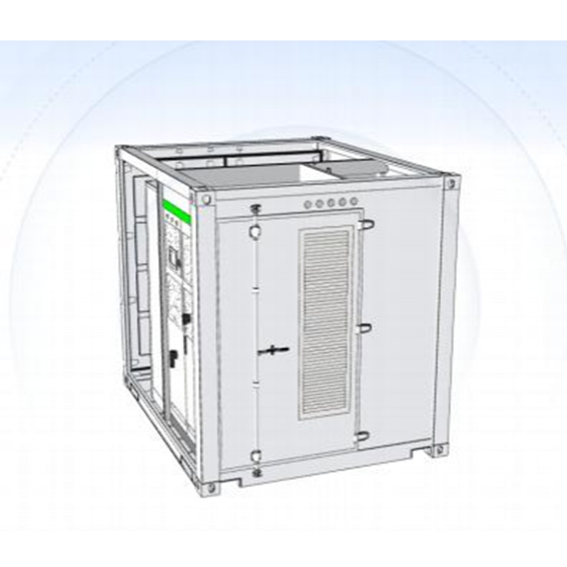
1.The all-in-one energy storage cabinet can improve the promotion and effective utilization of new energy such as photovoltaic and wind power, and meet various energy needs of customers. It is suitable for peak load shifting and valley filling,photovoltaic wind power consumption, demand limit, auxiliary light storage and charging system, backup power supply and other application scenarios.
The all-in-one energy storage cabinet selects 3.2V/280Ah LFP batteries (single module capacity of 14.34kWh) for energy storage ; The 1P15S battery configuration is used for a single cabinet (battery rack) with rated capacity of 215kWh;With one 100kW power conversion systems (PCS) and operating in air cooling mode; the system can automatically realize the charging and discharging adjustment of energy storage battery system in different application situations,and meet the technical requirements of power quality, command response, and power control;
● The all-in-one energy storage cabinet works in a three-level control mode, that is, BMU, BCMU, and energy management system (EMS),it combine the traditional three-level BAMS with EMS, which can not only realize the real-time monitoring and control from the cell to the system; simplify equipment management, efficient data transmission, effective utilization of resources, rapid control of energy, real-time event recording and multi-level joint protection. At the same time, it provides an integrated cabinet cloud management platform to meet the functions of real-time view, remote operation and maintenance, and revenue analysis between users and operation and maintenance personnel.
2. Functions and characteristics function
● Peak cutting and valley filling
It uses energy storage devices to discharge and supply power to the load during peak/off peak periods, and draws electricity from the grid during off peak periods to reduce peak/off peak load demand and save electricity costs.
● Distributed energy consumption
It can reduce the impact of distributed wind power generation on the power grid, promote the development of distributed wind energy with high penetration rate in the power grid, and reduce wind and light abandonment.
● Emergency backup power supply
When the system experiences poor power quality and can disconnect from the grid, it uses energy storage inverters to establish stable voltage through batteries to independently supply power to local important loads, providing emergency
characteristic.
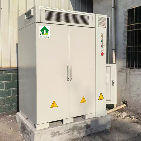
● Flexible
It supports overall lifting, adopts preinstalled testing and factory production
methods, supports independent work, supports centralized parallel operation, and meets the needs of different customers and scenarios.
● Reliable
It is equipped with smoke detectors, temperature detectors, and aerosol fire
extinguishing devices, which can provide early warning and extinguishing in case of a fire, ensuring safety.
● Efficient
It adopts a highly available integrated design architecture, which improves the
overall data exchange efficiency of the system, ensures fast power switching and real-time monitoring of the status of the integrated cabinet, and achieves efficient operation.
● Intelligent
It is equipped with a cloud based control and mobile monitoring platform, which can analyze the real-time operation status and revenue data of the integrated
cabinet. Equipped with real-time alert SMS push and auxiliary operation and maintenance inspection functions, achieving intelligent operation and
maintenance.
3. Technical parameter
|
Product model |
XHY-E100-215 |
|
Battery side parameters (DC DC) |
|
|
Nominal capacity (kWh) |
215 |
|
Nominal Voltage (VDC) |
768 |
|
Voltage Range (VDC) |
600~900 |
|
Cell specifications |
3.2V/280Ah |
|
Battery type |
Lithium iron phosphate (LFP) |
|
Module specifications |
1P240S |
|
Grid connection side parameters (AC/ AC) |
|
|
Nominal power (kW) |
100 |
|
Max power (kW) |
110 |
|
Nominal Voltage (VAC) |
400 |
|
Mode of connection |
Three-phase four-wire (3W + N + |
|
|
PE) |
|
Frequency (Hz) |
50/60±2.5 |
|
Power factor |
-0.99~+0.00 |
|
Reactive power is of an adjustable power range |
-100%~100% |
|
Total harmonic current distortion rate(THD) |
≤3% (fully-load) |
|
Underlying parameter |
|
|
Protection grade |
IP54 |
|
Altitude |
≤2000 m |
|
Working humidity |
≤95% RH without condensation |
|
Working temperature |
-20~50°C |
|
Cooling-down method |
Air cooled(PCS),water cooled(battery) |
|
Noise |
≤75db |
|
Communication interface |
RJ45/RS485/4G |
|
Dimensions (W * D * H) |
1500*1500*2300 mm (single cabinet) |
|
Weight (kg) |
~3000 |
4. Running mode
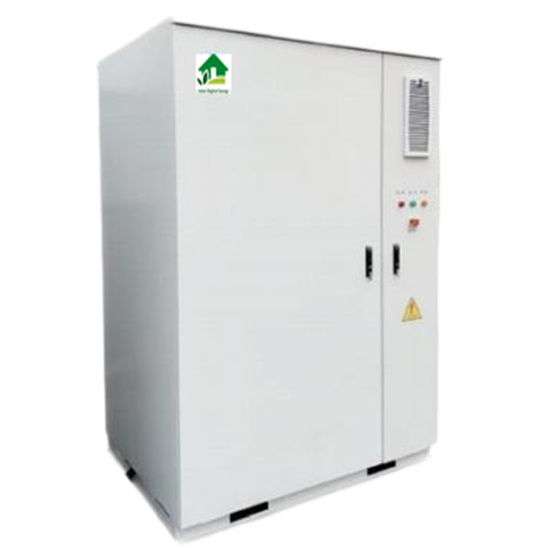
The all-in-one energy storage cabinet supports single cabinet operation mode and multi-cabinet operation mode (K10 screen optional).
● Single-cabinet operation mode
For the application scenario of 100kW/215kWh energy storage capacity demand,the system can be configured with a single outdoor battery cabinet, which is equipped with an energy management system (EMS) and grid connected to achieve independent control and operation, while uploading data to the management system.
● Multi-cabinet operation mode
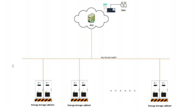
According to the application scenarios of multiple 100kW/215kWh energy storage capacity requirements, the system can be configured with multiple outdoor cabinets and corresponding grid connected cabinets, multiple cabinets can cooperate with each other to realize the functions of data access and energy management, realize the grid connection and coordinated control and operation of multiple battery cabinets, and send the data to the cloud management system.
5. Introduction to cabinet body
Considering the technology maturity, battery life, energy conversion efficiency and energy density factors, this system selects 3.2V/280Ah LPF, and adopts self-developed integrated battery management system (BMS), which is more efficient and stable, with air cooling control technology to ensure the safety and reliability of the battery.
cell
The battery cabinet consists of 1 battery cluster, consisting of 15 battery packs (PACK), each of which contains 16series cells
|
Order number |
Project |
Specifications |
|
|
Module basic parameters |
|||
|
1 |
Burst mode |
1P16 S |
|
|
2 |
Nominal voltage |
58.4VDC |
|
|
3 |
Nominal capacity |
280Ah |
100%DOD,0.5P1,2 5 ±2 ℃ (ambient temperature), 16 ± 2 ℃ (coolant input temperature) |
|
4 |
Nominal energy |
14.34kWh |
|
|
5 |
Nominal charge and discharge power |
7. 17kW |
|
|
6 |
Maximum charge and discharge current |
7. 17kW(Contin uous) |
|
|
7 |
Nominal charge and discharge current |
140A |
|
|
8 |
Maximum charge and discharge current |
179.2A |
|
|
9 |
Operating voltage range |
120V~ 175.2V |
Single voltage range 2.5V-3.65V |
|
10 |
Cell monthly self-discharge |
≤3.5% |
25 ± 2 ℃ , 50% SOC storage, 3 months after battery production |
|
Eenviromental parameter |
|||
|
1 |
Transport and months temperature (battery at 50%) |
Within 1month |
-30℃-45℃ |
Store ambient humidity, 65% RH, no condensation |
|
2 |
Within 6months |
-20℃~35℃ |
|
|
|
3 |
cooling-down method |
liqukd cooling |
|
|
|
General parameters |
||||
|
1 |
Overall dimensions (width *depth * height) |
792* 1089*250 mm (±4mm) |
|
|
|
2 |
insulation resistance |
≥500MΩ |
|
|
|
3 |
IP grade |
IP67 |
≤ 95% RH without condensation |
|
|
4 |
Communication interface &Protocol |
CANBUS2.0 |
|
|
|
5 |
Altitude |
≤2000m |
|
|
|
6 |
Product weight |
(100±5)kg |
|
|
high-voltage compartment
The equipment in the high voltage box includes secondary BCMU, 24V switching power supply, fuse, shunt, contactor, etc.
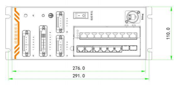
High pressure box shape
major function
● Cluster collection, battery cluster current collection, total voltage collection. ● Abnormal protection: Power-off protection when the battery state is abnormal ● Communication hub: collect BMU information down through BCMU and pass it to EMS up through LAN.
technical parameter
|
High pressure box parameters |
|
|
Applicable scene |
Inside the cabinet |
|
Nominal voltage |
832Vdc |
|
Nominal current |
140A |
|
Auxiliary rated voltage |
220V ,50Hz |
|
CI |
CAN, RJ45,RS485 |
|
Dimensions (W * D * H) |
480*565 *169.5mm |
|
Weight (approx) |
20kg |
|
Electrical interface, PCS |
PCS- -which works together with the PCS + |
|
Electrical interface battery module |
The BAT-works together with the BAT + |
Battery management system
The protection and monitoring function of the battery system is realized by the BMS battery management system, and the BMS system of the battery system is managed in two levels, namely BMU and BCMU respectively.
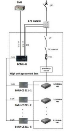
Battery management system architecture
●BMU function
It can monitor the voltage, temperature, and total voltage of individual cells and trays, and the above information is transmitted to the superior BCMU through CAN protocol, which can control the voltage balance of the single cell.
●BCMU function
BCMU (rack level, built in high voltage box) detects the total voltage and current of the whole battery, and transmits the above information to EMS in real time
through TCP protocol. It can display the capacity and health state of battery charge and discharge, the prediction of power, the calculation of internal
resistance, and control the balance of relay switch and disk level unit voltage.
● BMS technical parameters
|
Order number |
Project |
Specificati ons |
Remarks |
|
Cell voltage sampling |
|||
|
1 |
Scope |
0-5V |
|
|
2 |
Accuracy |
±3mV |
|
|
3 |
Number of channels sampled by monomer voltage |
16 |
Up to 52 channels of support, which can be matched on demand |
||
|
Battery temperature sampling |
|||||
|
1 |
Scope |
-40~120℃ |
|
||
|
2 |
accuracy |
-25℃~65℃ |
≤±1℃ |
|
|
|
From-40 to-20 or 65 to 125℃ |
≤±2℃ |
||||
|
3 |
Number of channels sampled by monomer temperature |
15 |
Up to 32 roads are supported |
||
|
Group end voltage sampling |
|||||
|
1 |
Scope |
0~ 1500V |
|
||
|
2 |
Accuracy |
≤1% FSR |
|
||
|
3 |
Period |
≤100ms |
|
||
|
Group-end current sampling |
|||||
|
1 |
Scope |
± 1000 A |
|
||
|
2 |
Accuracy |
≤1% FSR |
|
||
|
3 |
Period |
≤50ms |
|
||
|
Enviromental parameter |
|||||
|
1 |
Storage temperature |
-40~ +85℃ |
|
||
|
2 |
Working temperature |
-40~ +65℃ |
|
||
|
3 |
Working voltage |
9~32VDC |
|
||
|
Other parameters |
|||||
|
1 |
The SOC estimation accuracy |
≤±5% |
|
||
|
2 |
The SOE estimation accuracy |
≤±5% |
|
||
|
3 |
Equalizing current |
100mA( V bat/33R) |
|
||
|
4 |
Insulation detection |
0 ~ 10M Ω |
And 95% RH without condensation |
||
|
5 |
Communication interface |
BMU |
CAN |
|
|
|
BCMU |
CAN/RS485/R J45 |
||||
l Energy storage converter system (PCS)
The all-in-one energy storage cabinet adopts a 100kW modular energy storage
converter, which can realize the charge and discharge function of the battery
system in different application occasions. It has two operation modes: grid-
connected and off-grid; support multi-machine parallel operation, good capacity
expansion, and real-time fault protection according to grid-connected side voltage, frequency and its own operating status.
l Technical parameters of the PCS
|
DC side parameters (DC /DC) |
|
|
DC voltage range |
DC600V~950V |
|
DC maximum current |
192 A |
|
Nominal DC power |
100kW |
|
Stable pressure accuracy |
≤±2% |
|
Stable flow accuracy |
≤±5% |
|
Communication grid connection parameters |
|
|
Nominal power |
100 kW |
|
Overload capacity |
1.1 times long term, 1.2 x 1min |
|
Nominal voltage |
AC 400V |
|
Nominal output current |
145 A |
|
Communication access mode |
Three phase four line |
|
Power grid voltage range |
400V(-20%~+15%) |
|
Power grid frequency range |
50Hz/60Hz±2.5Hz |
|
Total harmonic current distortion rate (THD) |
3% (full load) |
|
Power factor |
-0.99~+0.99 |
|
Charge-discharge conversion time |
<100ms |
|
AC off-grid parameters |
|
|
AC off-grid voltage |
AC400V |
|
AC voltage range |
AC400V±3% |
|
AC off-grid frequency |
50Hz/60Hz |
|
Off-grid output of the THDU |
3% (Linear load) |
|
Unbalanced load capacity |
100% |
|
Other parameters |
|
|
Maximum conversion efficiency |
≥98% |
|
Allow ambient temperature |
-20℃ ~50℃ (> 45℃ required) |
|
Allow relative humidity |
≤95% |
|
Noise |
≤75dB |
|
Levels of protection |
IP20 |
|
Height |
More than 2000 meters need to be used down |
|
Dimensions (W * H * D) |
480*186*620mm |
|
Weight (approx) |
50kg |
|
Cooling-down method |
air blast cooling |
|
BMS CI |
CAN |
|
EMS CI |
Network port / RS485 |
Air cooling system
The air cooling unit adopts integrated design, all modules are packaged in a
chassis, convenient installation and space saving. The air cooling unit is used to adjust the temperature of the battery module in the integrated cabinet to ensure the final operation of the cell in the appropriate temperature range and provide the system efficiency.
● Intelligent temperature control
The unit monitors the outlet temperature in real time. When the outlet
temperature is higher than the refrigeration setting point and meets the cooling opening point, the unit starts the heating function; When the heating temperature is suitable, only activate the electronic water pump to meet the battery cooling at
the lower heat load and reduce the power consumption.
● remote monitor and control
The unit is connected with the EMS system of the integrated cabinet through
RS485 / CAN. Through message interaction, the unit can be connected remotely through EMS to query the running status of each component of the air conditioning unit and set control parameters.
● Technical parameters of the liquid-cooling system
|
Parameters of air cooling system |
|
|
Use ambient temperature |
-30~55℃ |
|
Use ambient humidity |
0~95%RH |
|
Nominal refrigeration volume |
5kW |
|
Heating capacity |
2kW |
|
Noise |
≤±5% |
|
Electrical protection grade |
IP55 |
|
Internal control voltage |
DC24V |
|
Weight (approx) |
75kg |
|
Communication protocol interface |
RS485 |
security system
-fire extinguisher system-
● The system is equipped with gas detector and temperature detector, which can realize the detection of various conditions of thermal runaway of the battery.
● The system has intelligent linkage function, when the integrated cabinet due to overload, short circuit and other reasons caused by the battery environment
rapid heating or ignition, electrolyte leakage produces toxic and flammable gas, the system can quickly detect, the signal to the monitoring system, the signal push operation and maintenance personnel and the integrated cabinet can
connect, dc gas connection disconnected in time.
● The system is equipped with aerosol (customizable according to the user) fire extinguishing device, after receiving the start signal sent out by the detector to achieve self-fire extinguishing.
-Pressure relief system-
● The system has pressure relief and explosion-proof function, when the pressure in the cabinet reaches the limit value, can quickly and automatically open the exhaust cover, so that the high pressure or dangerous gas inside the body can be quickly discharged through the exhaust valve, so as to achieve the pressure reduction, discharge dangerous gas.
-Intelligent dehumidification system-
● The system has humidity detection function, the integrated cabinet equipped with temperature and humidity detection device can detect the humidity in the cabinet in real time, and through RS485 to connect the collected information in real time.
●The system has intelligent dehumid ification function, EMS real-time detection of humidity information in the cabinet, according to the humidity range value of the cabinet operation, intelligent control of the dehumidifier, to ensure the safe
operation of the cabinet.
Energy management system
Energy management system(EMS) has a complete set of energy management solutions, which are connected to PCS, BMS, liquid cooling system, safety system and electricity meter in the integrated cabinet. It can access the
external photovoltaic, load, grid-connected electric energy meter and other
systems according to the actual situation on the site to ensure the coordinated operation of the system in the state of parallel and off-grid. The main hardware components are the energy controller (SECU-100) and the switch.

Energy management unit
The core component of the energy management unit is the energy controller (SECU-100), and the technical parameters are as follows:
|
The SECU-100 parameters |
|||||
|
Project |
Parameter |
Remarks |
|||
|
least value |
Standard configuration |
Crest value |
Unit |
||
|
internet access |
|
2 |
2 |
road |
10M / 100M / 1000M Adaptive Ethernet network interface. |
|
CAN |
|
1 |
2 |
road |
The maximum isolated communication rate is 1000 Kb/s and the default communication rate is 250 kb / s |
|
RS485 |
4 |
5 |
5 |
road |
Quarantine the communication, and the default communication rate is 9600 |
|
DO |
|
4 |
4 |
road |
1A/ 30VDC/ 1A/ 250VAC |
|
DI |
|
4 |
4 |
road |
|
|
4G module |
|
|
1 |
individ ual |
(Optional) |
|
SD block |
|
- |
1 |
individ ual |
(Optional) |
|
Point measureme nt |
|
- |
6000 |
|
|
|
rated voltage |
18 |
24 |
36 |
Vdc |
|
|
rated dissipation |
- |
3 |
- |
W |
|
|
communicat ing protocol |
IEC 60870-5-104 ,Modbus/RTU, Modbus/TCP ,DLT645 ,MQTT |
||||
|
resource |
ARM platform, Cortex A7 kernel; 512MB DDR3; 1GB eMMC; Linux |
||||
l Measurement and monitoring function
The system monitors real-time data information of station equipment (including photovoltaic systems, loads, energy storage systems, electricity
meters, circuit breaker status, etc.).
Simulation measurement: collect and process the voltage, current, active power, reactive power, main transformer temperature, DC voltage, feed outlet frequency, phase and power factor of all controlled stations; state measurement: access AC / DC circuit breaker information, fault signal, equipment operation alarm signal, etc.
l Data processing and analysis function
The system realizes real-time processing of data information, such as remote communication processing includes: remote signal reverse and remote signal change, which can be automatically identified according to the total accident
signal and protection signal; analysis and statistical functions of the integrated cabinet, total charge and discharge efficiency, charge and discharge power, charge and discharge income, etc.
l Operation control function
The system realizes real-time control of energy storage charging
and discharging power, circuit breaker opening and closing, air conditioning
switch on and off, etc. Ensure the stable, efficient and safe operation of the entire site.
l Event alarm function
The system provides an open and intelligent event alarm function, which queries the alarm information of the integrated cabinet by type and alarm source, and the system can provide a unified and permanent storage of all the event alarm
information.
l One-click configuration
The system classifies and builds the model according to the integrated cabinet equipment. The system has the equipment model of multiple manufacturers in the industry. The operator can complete all the detailed configuration of the equipment through one-key model configuration, which improves the accuracy of the configuration and the efficiency of debugging.
l human-computer interface
The system has embedded display interface, which provides operators with
intuitive graphical monitoring and operation interface: support wiring diagram,
telemetry table, remote communication table and other pictures, support to
display all measurement information with different images; support real-time trend curve; system support menu (including configurable right button menu, toolbar), hot spot, tree catalog and other operation modes; and support control through
pictures, including remote control and remote adjustment.
l Remote movement and forwarding function
The system supports the data forwarding function to other systems, and uses the bottom broadband efficient communication protocol to forward the data to the flat Dan energy storage cloud management platform, and also supports the data
ethernet, 4G and other ways to third-party platforms.
l Multi-level joint protection strategy
The system can monitor photovoltaic systems, loads, and energy storage
systems (including BAMS, PCS, AC circuit breaker, fire protection, temperature and humidity sensors and other equipment), electricity meters and other
equipment. Monitor the communication and fault information of these devices. According to the severity of the fault, it is divided into three categories: mild,
severe fault and critical fault. Different protection operations are carried out for different faults, and the control system is kept by standby or shutdown to ensure the safe and reliable normal operation of the whole system.
l Peak-shifting and valley-filling control
The operation and maintenance personnel can develop a reasonable daily power generation plan based on the local peak and valley electricity prices and time, and use the special configuration tools to define the charge and discharge period and the corresponding charge and discharge power value of the station monitoring
system to conduct the charge and discharge management and charge and discharge control of the whole station energy storage system;
l Demand control
The system can monitor the power value of the grid connection point in real time, and effectively control the grid connection point power within the set range by
adjusting the charging and discharging power of the energy storage system.
According to the policies of different regions, the demand and
electricity charge management and demand side management are auxiliary profit points, by helping users to reduce the demand and electricity charges, to obtain additional profit points;
l Inverse power protection control
The system monitors the power value of the grid connection point in real-time, and adjusts the charging and discharging power of the energy storage system to
ensure that the grid connection point power is not lower than the reverse power protection limit value, can prevent the energy storage system to send power to the system, and have the function of low frequency and low voltage d isassembly
energy storage system, improve the safety of the system operation;
l Micro-grid economic operation control
When the micro-grid is connected to the grid, the system aims to maximize the energy utilization efficiency and minimize operating costs of the entire system while ensuring the safe operation of the micro-grid. It fully utilizes renewable
energy to achieve complementary power generation of multiple energy sources, ensuring the optimal economic operation of the entire micro-grid.
l off-grid control
When the external mains power drops, the system controls the energy storage
converter (Pcs) to operate in V / f mode, to provide voltage and frequency support for the system, and to ensure that the energy storage power can be fully utilized to realize the power supply of the system load during the external power failure.
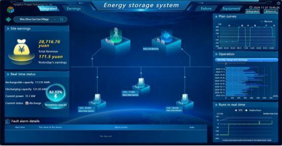
6. Energy storage cloud management platform
● Pingdan energy storage cloud management platform is a collection of application services such as data aggregation display and operation analysis of the energy storage system. Based on the micro-service architecture, it can be
flexibly deployed on the public cloud or private cloud.
● The platform supports the operation data traceability and fault query of the energy storage power station at any time period in the past.
● The platform empowers decision-making and risk prediction for energy storage power stations, achieving true unmanned operation of energy storage power
stations.
● The energy storage integrated cabinet uploads the data to the cloud server through 4G for users to view in the form of WEB and APP.
Energy storage cloud management platform access Energy Storage Cloud management platform- -WEB page.
Real-time information monitoring of energy storage power station: site information, battery information, converter information, etc.
Operation and maintenance of energy storage power station: revenue and power quantity, efficiency analysis, etc.
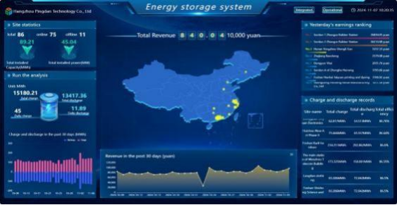
Regional Overview Map
Site Overview Map
Energy storage cloud management platform- -App
The mobile terminal of the energy storage cloud management platform realizes data aggregation display, operation analysis, operation management and fault alarm.

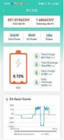
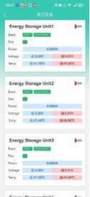
Mobile phone APP display
We answer most inquiries in less than 3 hours during our normal business hours.
Categories
We Are A Professional Manufacturer Of 5w To 50kw All Kinds Of Solar Power System Home ,Solar Kit Etc.

We Are A Professional Manufacturer Of 5w To 50kw All Kinds Of Solar Power System Home ,Solar Kit Etc.
Solar Digital Energy Company Co.,ltd can Supply 6w 14w 21w 40w 60w 80w 100w 120w 160w 200w Solar Backpack Charger,Solar Panel Backpack , Solar Energy Bag,Solar Charging Bag,Solar Panel Carry Bag.
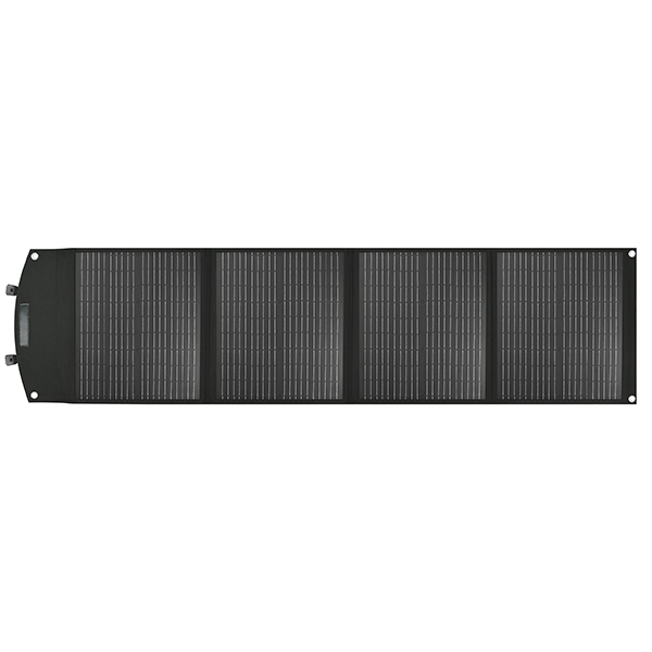
We're Folding Solar Panel,Foldable Solar Panel ,Solar Back Pack Supplier And Exporter.

For inquiries about our products or pricelist, please leave to us and we will be in touch within 24 hours.
 Room 1304 Building A Guanlan jieshun Technology Center GuanshengSechond Rd, Shenzhen, China